



2026年11月9日
Double-Pitch Solar Carport Design: Engineering Guide
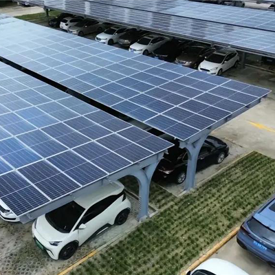
A double-pitch solar carport — also called a gable, duo-pitch or two-sided solar carport — looks simple. Two sloping PV planes meeting at a ridge, a row of columns, cars underneath. That simplicity is exactly what gets projects into trouble. The roof is open on all four sides, so wind acts on it the way it acts on nothing else in your building portfolio; the panels carry live loads they were never sold for; and a rain shadow across one string can cost you more annual energy than the entire steel budget.
This guide walks through the four design pillars: structural and foundation safety, PV and electrical design, functional and vehicle safety, and lifecycle cost and maintenance — plus the design workflow we recommend before anyone signs a procurement contract.
What “Double-Pitch” Actually Means for Your Design
Unlike a mono-pitch (single-slope) carport, a double-pitch carport splits the canopy into two opposing slopes, typically supported by a central column line — often a “Y”-shaped column with cantilevers reaching out on both sides. Three consequences follow directly, and every one of them is a design decision rather than a detail:
- Both roof planes can generate. One face can be oriented for maximum annual yield while the second face captures morning or evening load, which is useful when the carport feeds EV chargers.
- The ridge becomes the critical structural line. It is where the two slopes connect, where drainage is collected, and — as wind-tunnel testing on double-pitch PV carports has shown — where the peak suction pressure appears.
- The eaves carry the highest positive pressure. Edge and corner zones on an open canopy are the origin points for peeling failure, which is why fastener layout at the perimeter matters more than panel count in the middle of the field.
If you are additionally specifying bifacial modules, the carport is one of the most favourable mounting typologies for rear-side energy, since the open ground plane under the canopy returns reflected light. That gain is real, but it is governed by tilt, mounting height and rear-side obstructions — cars, columns and cable trays all shade the rear cell area, so it must be modelled rather than assumed.
Part 1 — Structural and Foundation Design (The Non-Negotiable Layer)
Structural engineering is the part of a solar carport project that cannot be value-engineered after the fact. Everything else can be upgraded; a torn-off canopy cannot.
1. Load calculations must be exact
| Load case | What it includes | Why it fails projects |
| Dead load | PV modules, mounting/racking system, roof framing, any metal roofing deck | Usually the easiest to get right — and the least likely to be the governing case |
| Live load | Maintenance personnel, tools, accumulated dust and debris | Frequently omitted entirely on carports, because nobody “designed” a roof for people to walk on |
| Wind load | Basic wind pressure for the site, plus pressure on the windward face, suction on the leeward and side faces, and net uplift | The governing load case for almost every double-pitch carport |
| Snow load | Basic snow pressure plus unbalanced / drifting accumulation behind ridges and parapets | In cold regions, snow at the ridge line can dominate the design |
| Seismic load | Horizontal inertial forces in earthquake-resistant design zones | Required by code in seismic regions; often discovered late in permitting |
For wind and snow, use the local code-mandated return period for the site. In practice that is typically a 50-year return period basic wind pressure and basic snow pressure, read from the hazard map published under your national or regional loading code — ASCE 7 in much of North America, Eurocode EN 1991-1-4 in Europe, GB 50009 in China. Do not import a value from a neighbouring project or a supplier’s standard datasheet.
Two points specific to double-pitch carports deserve emphasis:
- Openness changes everything. A carport is a four-side-open canopy, not an enclosed building. Pressure coefficients from tables written for enclosed gable roofs are not automatically valid. Research on 1:50-scale double-pitch PV carport models found that the maximum uplift occurs at the ridge, the maximum positive pressure at the eaves, and that extreme suction increases as roof pitch increases. The same work flagged that oblique (diagonal) wind can be the critical direction while code values derived from orthogonal cases may be non-conservative for those local zones. Design for the worst wind direction, not the easiest one to look up.
- Tilt is a structural input, not only an energy input. A steeper plane catches more uplift. Every degree you add for yield is subtracted from your wind margin unless the structure is resized to match.
2. Foundations: design for pull-out, not just compression
Columns push down. Wind pulls up. The uplift case is what governs a carport foundation, and it is the one most often under-designed.
- Foundation type follows the geotechnical report, not habit: isolated pad footings where soil bearing is good; pile foundations or prestressed concrete pipe piles in soft ground.
- Verify overturning and pull-out for the full canopy, including the end bays where a single column resists the largest cantilevered moment.
- Concrete strength and curing must be documented — early-age cracking in a shallow pad under cyclic uplift is a long-term durability problem, not a cosmetic one.
- Check the anchor bolts, not only the concrete. Bolt grade, embedment depth, edge distance and torque verification during installation are the difference between a code-compliant calculation and a code-compliant building.
3. Structural layout and material selection
Column spacing (span). Spans in the region of 8–9 m are commonly used because they buy wider, more usable parking bays and fewer columns in the driving lanes. Longer span means heavier members, deeper deflection control and higher cost, so the span is optimised, not chosen — the economic sweet spot sits where steel tonnage, bay utility and foundation size intersect.
Roof pitch. Balance three competing demands: maximum annual irradiance for the latitude, self-cleaning and drainage, and wind uplift. A low-pitch canopy (in the single-digit range) can meaningfully reduce wind loading at the cost of some yield and drainage performance; a high-pitch canopy does the reverse. Model both, then decide.
Primary framing. Hot-dip galvanised steel is the mainstream choice — high strength, predictable cost, and a mature supply chain. The condition is galvanising thickness: it must meet the specified coating mass for the site’s corrosion category, because a carport cannot be re-galvanised in the field. Aluminium is the alternative where aesthetics, salt-air exposure or a coastal environment justify the premium.
Purlins and secondary members. Cold-formed C-section or Z-section purlins are typical. Their stiffness — not just their strength — controls performance: an under-stiff purlin deflects under wind pressure, and deflection transfers into glass and frame stress at the module clamp, which is where cell micro-cracking and warranty claims begin.
Part 2 — Photovoltaic and Electrical System Design
4. Module layout and shading avoidance
On a double-pitch canopy with a central column line, shading is a geometry problem you solve at the layout stage, not a repair you attempt at commissioning.
- Inter-row and cross-plane shading. Where two arrays face each other across the ridge, or where a canopied row is close to an adjacent ground structure, verify early-morning and late-afternoon shadow paths. Shading does not just reduce output — it drives hot-spot risk on the shaded cells and can pull down a whole string.
- Module selection. High-efficiency monocrystalline modules (PERC and the newer TOPCon generations) are the current mainstream. On a carport, roof area is the scarce resource, so a higher-efficiency module that packs more watts into the same canopy footprint typically improves project returns more than a larger structure does.
- Bifacial specifics. Where the design allows it, model rear-side irradiance explicitly and set mounting height, tilt and pitch together. Consider row spacing through a ground-cover-ratio logic so that the shading loss you accept is the one you chose, not the one you inherited.
5. Inverter selection and placement
- String inverters are the default for carports: they adapt flexibly to different orientations across the two roof planes and to partial-shading behaviour. On large, regular layouts, central or distributed (集散式) configurations can compete on cost per watt.
- Location matters. Mount inverters in shaded, ventilated positions — commonly on the columns — away from direct solar radiation, splash zone and standing water, and within reach of a maintenance ladder or vehicle.
- DC and AC cabling must be UV-resistant, weather-rated and flame-retardant PV cable throughout. Conduit routing should be planned so that no cable run sits in a ponding path or against a hot metal surface.
6. Lightning protection and grounding
A solar carport is a tall, isolated, conductive structure sitting in an open parking lot. It is a lightning target by geography.
- Air termination: use the metallic canopy surface or a purpose-installed lightning belt as the air-termination system.
- Down conductors: use the main reinforcement inside structural columns, or dedicated flat steel, routed per code.
- Grounding system: a complete equipotential-bonding network and ground grid, with earth resistance meeting the specified requirement — commonly quoted at ≤4 Ω, and to be verified against your local code and soil conditions rather than assumed.
Bonding is as important as grounding: every module frame, rail, purlin, column and inverter enclosure belongs in the same equipotential system. Unbonded gaps are where arcing and touch-voltage hazards appear.
Part 3 — Functional and Safety Details
7. Vehicle and pedestrian safety
- Clear height. The lowest soffit point must clear the vehicles that will actually use the lot — including SUVs, vans and high-roof trucks. Below roughly 2.5 m is a problem; 2.8–3.5 m is the practical band for most commercial lots, with fire-lane and local code minimums checked separately.
- Fall-protection / drop-prevention design. Every module, bracket and fastener must be engineered against release. Bolted connections should use prevailing-torque or otherwise certified locking, and the design should assume decades of thermal cycling and vibration from traffic underneath.
- Drainage. Provide adequate fall on the canopy plane, gutters at the ridge and eaves, and downpipes sized for the design rainfall intensity. Ponding adds dead load, accelerates corrosion at lap joints, and creates standing water that breeds insects in the lot.
8. EV charging integration
Design for chargers on day one, even if they are not purchased on day one.
- Pre-embedded conduit. Route and bury power and communication pathways during the civil works. Retrofitting means trenching a finished, operating car park — a cost and an outage you can entirely avoid.
- Bay layout. Reserve space at charging bays for cable reach, pedestal or wall-box mounting, and ADA/clearance requirements, and plan markings and enforcement logic that keeps non-charging vehicles out of those bays.
- Capacity headroom. Size the switchboard and incoming feeder for a realistic future charger count, not just the current order.
9. Lighting and surveillance
- Night illumination via LED fixtures on photocell or timer control — a safety requirement for a lit parking facility and, practically, a precondition for EV charging after dark.
- CCTV coverage deters theft and vandalism of modules and copper, and gives your O&M team remote evidence when an alarm fires.
Part 4 — Economics and Long-Term Maintenance
- Cost optimisation happens where it does not touch safety: lightweight member profiles, rationalised spans, standardised connection details, and equipment chosen on lifecycle value rather than lowest invoice price. Steel tonnage per kW is a legitimate KPI to tune — anchor-bolt grade is not.
- Access for O&M. Design the cleaning and inspection path before construction: walkway positions, roof anchor points for fall-arrest, ladder and lift access, and clearances above parked vehicles.
- Cleaning plan. Locate a water take-off point in the lot, and decide early between manual washing and automated cleaning hardware. On a carport, dust and pollutant loading above traffic lanes is heavier than on a clean rooftop, so soiling loss is a recurring line item in your financial model.
The Design Workflow We Recommend
- Site survey — plot dimensions and boundaries, geotechnical conditions, and local climate data (wind, snow, solar irradiance).
- Concept design — carport layout, column spacing, roof pitch, module arrangement, electrical architecture.
- Structural calculation and drawings — carried out by a licensed structural engineer, covering every load combination including uplift and oblique wind.
- Electrical design — single-line diagrams, string layout, cable schedule, lightning protection and grounding design.
- Construction and commissioning — qualified contractor, strict as-built adherence to the designed drawings, documented acceptance testing (torque verification, earth-resistance measurement, insulation and functional tests).
Five Mistakes That Put Double-Pitch Carports at Risk
- Using enclosed-building pressure coefficients for a four-side-open canopy.
- Designing the foundation for gravity load and checking uplift only on paper.
- Raising roof pitch for energy yield without resizing for the extra suction at the ridge.
- Retrofitting EV charging conduit after paving, at several times the embedded cost.
- Skipping the geotechnical report and letting the pile contractor guess.
FAQ
Is a double-pitch solar carport better than a single-slope one?
For two-sided parking rows it is usually the more space-efficient structure, because one central column line serves bays on both sides. Structurally it is more demanding: the ridge and eave zones govern wind design, and the layout has to manage cross-plane shading.
For two-sided parking rows it is usually the more space-efficient structure, because one central column line serves bays on both sides. Structurally it is more demanding: the ridge and eave zones govern wind design, and the layout has to manage cross-plane shading.
What wind load does a solar carport have to withstand?
It is site-specific. Design to the basic wind pressure your code assigns to the location for the required return period — commonly a 50-year event — and apply the pressure coefficients for an open, low-rise canopy rather than copying values from an enclosed building.
It is site-specific. Design to the basic wind pressure your code assigns to the location for the required return period — commonly a 50-year event — and apply the pressure coefficients for an open, low-rise canopy rather than copying values from an enclosed building.
How high does a solar carport need to be?
Enough for the tallest vehicle expected to enter. Keep the lowest soffit above roughly 2.5 m, and 2.8–3.5 m for commercial lots, subject to local code and fire-access requirements.
Enough for the tallest vehicle expected to enter. Keep the lowest soffit above roughly 2.5 m, and 2.8–3.5 m for commercial lots, subject to local code and fire-access requirements.
Can a solar carport charge EVs?
That is one of its strongest use cases — the canopy generates during the day exactly when vehicles are parked. The electrical and civil design has to reserve conduit, switchboard capacity and bay geometry for chargers from the first drawing.
That is one of its strongest use cases — the canopy generates during the day exactly when vehicles are parked. The electrical and civil design has to reserve conduit, switchboard capacity and bay geometry for chargers from the first drawing.
Should I use bifacial modules on a carport?
Carports are a good bifacial application because the open ground returns light to the rear cell area. Model rear-side irradiance — including shading from parked cars and columns — before committing, since height, tilt and pitch must be set together.
Carports are a good bifacial application because the open ground returns light to the rear cell area. Model rear-side irradiance — including shading from parked cars and columns — before committing, since height, tilt and pitch must be set together.
Bottom Line
A double-pitch solar carport earns its keep on the strength of its least visible components: the uplift capacity of its foundations, the wind coefficients chosen for an open canopy, the bonding continuity of its grounding grid, and the conduit that was buried before the asphalt went down. Commission the structural and electrical design from an experienced PV and structural engineering team, verify every load case against your local code and site conditions, and refuse any cost cut that lands on those four items. Saving money on structure is not economy — it is deferred failure.


