


Solar Bracket Foundations: Why the Base Decides the Entire System
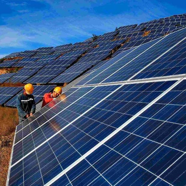
A solar bracket looks simple. Two posts, a rail, a few clamps, and a panel tilted toward the sun. But the part of the system that actually fails is rarely the bracket itself — it is what holds the bracket to the earth. Industry reporting puts a number on that exposure: U.S. solar facilities lost $5,720 per megawatt in 2024 due to equipment losses, with weather a key risk factor, against a backdrop in which 2023 was the costliest natural-disaster year in U.S. history at more than half a trillion dollars (pv magazine USA). Panels are replaceable. A solar bracket that has been pulled out of the ground, twisted by differential settlement, or corroded at its base plate is a structural event, not a maintenance ticket. This guide explains why the foundation is the governing design decision for any solar bracket, then walks through the five main foundation families — driven piles, ground screws, concrete foundations, ballasted systems and rock anchors — with an honest comparison of where each one wins and where each one fails.
What Is a Solar Bracket Foundation?
A solar bracket foundation is the structural element that transfers every load from the mounting system into the ground (or onto a roof deck or slab) without exceeding the soil’s capacity or the fastener’s strength. Those loads include:
- Dead load — the weight of the modules, rails, posts and hardware.
- Wind load — uplift, drag and downward pressure. A tilted solar panel behaves aerodynamically like an airfoil, and uplift is typically the most critical force because it actively tries to pull the array off its mounting (Anern PV racking engineering guide).
- Snow load — sustained downward compression in northern latitudes.
- Seismic load — lateral and vertical forces, relevant in active regions.
- Thermal and adfreeze effects — including the stress from the bond between frozen soil and the foundation surface (pv magazine USA).
In most ground-mount and tracker installations, wind governs the structural design, exceeding snow and other cases (PVRack wind load calculation guide). That single fact drives everything below: a solar bracket foundation is designed first as an anti-uplift device, and only second as a weight-bearing device.
Why the Foundation Matters More Than the Bracket
1. It is the only part you cannot easily repair
Aluminium rails can be unbolted. Clamps can be retightened. A foundation that settles, pulls out or cracks mid-life is buried work — excavating, re-pouring or re-driving under a live array costs far more than getting it right the first time.
2. It controls the tilt geometry, and therefore the energy yield
A solar bracket set at a designed tilt angle only delivers that angle if every post stays at the same height and plumb. Differential settlement — one post sinking faster than its neighbour — twists the superstructure above it. Where a ground screw settles slightly, an O&M crew can often unbolt the racking flange, adjust the bracket height on the screw’s slotted holes and re-level the array. Where a heavy concrete pier settles unevenly, adjustment is much harder, sometimes requiring disassembly of the tracker row and concrete shimming to restore geometric alignment (PVRack). That adjustability is a direct yield argument, not just a convenience one.
3. It sets the project’s construction schedule
Concrete foundations introduce a curing bottleneck. The concrete must sit and harden for roughly 7 to 14 days before heavy steel racking or trackers can be bolted to it (PVRack). Ground screws and driven piles are load-bearing almost immediately. On a fast-track build, that difference is measured in weeks of equipment rental, construction-loan interest and delayed grid interconnection.
4. It determines end-of-life cost
At year 25 the divergence is stark. A ground screw is cleanly backed out of the earth, leaving the site ready for immediate agricultural use, and the steel can be salvaged. A concrete foundation must be jackhammered, excavated and hauled to a landfill — a significant negative capital event at the end of the project’s life (PVRack). For leased farmland or agrivoltaic sites with remediation clauses, this can be decisive on its own.
5. It is where corrosion starts
Corrosion typically occurs at welds, from the electrochemical process of two or more metals in electrical contact in the presence of moisture — especially salt water or acid rain — and where soil has higher acidity. Mitigation includes sacrificial steel, coating foundation materials, and cathodic protection (pv magazine USA). A beautifully engineered solar bracket bolted to an unprotected base in acidic soil will still fail. Design note. Under ASCE 7-22, design provisions for rooftop-mounted photovoltaic panels and their attachments are covered in Section 13.6.12 for seismic loading and in Chapters 29 through 31 for wind loading, with additional guidance in SEAOC PV2-2017 (UpCodes). ASCE 7-22 also includes specific provisions for rooftop panels under conditions not covered in Chapter 29, including ballasted panels within defined tilt ranges (UpCodes). Confirm the governing edition and clauses with a licensed structural engineer for your jurisdiction.
The 5 Main Types of Solar Bracket Foundation
The recognised foundation families are driven piles, ground screws, concrete foundations, ballasted systems and rock anchors (PVRack solar foundation hub). Selection is a site-specific screening decision based on subsurface conditions, project loads, installation access, corrosion exposure, tolerances and the required verification plan — not a universal depth or cost rule.
1. Driven Piles
What it is. A steel pile hammered into the ground by a hydraulic impact driver. No excavation, no concrete, no spoil removal. Where it wins. Driven piles are a fast and cost-effective option for sites with favourable conditions, such as low refusal risk and shallow frost depths (pv magazine USA). They are the dominant foundation solution for utility-scale solar mounting worldwide, and at larger project scales the mobilisation cost of pile-driving equipment is amortised across enough points to make it the lowest-cost non-ballasted option in most soils (PVRack). Where it fails. Refusals — hitting rock, glacial cobble or dense hardpan — can wreak havoc on timelines and trigger millions in change orders (pv magazine USA). Piles are also noisy and vibration-intensive, which rules them out near hospitals, schools and protected habitats. Key caveat. Piles are cost-efficient if and only if installation is flawless (pv magazine USA). A bent or mis-driven pile is a rejected pile.
2. Ground Screws (Helical Piles / Screw Piles)
What it is. A heavy-duty steel pipe with a continuously welded helical flight, rotationally driven into the soil by a high-torque hydraulic rotary head — it threads itself into the earth and creates an immediate mechanical lock, with no concrete pouring or curing. How it resists load. The primary mechanism relies on the surface area of the helical flights, which engage a broad cone of undisturbed soil and generate resistance against both downward compression and upward tension. Because installation is torque-controlled, operators can verify the load-bearing capacity of every individual screw in real time by measuring hydraulic pressure (PVRack). Where it wins. – Speed. A single crew can install roughly 100 to 200 screws per day, immediately ready for racking (PVRack). – Tricky ground. Ground screws provide stability and reduce risk on projects with difficult subsurfaces, deep frost depths and rocky terrain (pv magazine USA). – Soft soil. In soft, sandy or marshy soils, ground screws often resist differential settlement more effectively than heavy concrete piers, which can sink unevenly under their own weight (PVRack). – Removability. Fully removable at end of life, lowering decommissioning cost and suiting agrivoltaic or leased-land sites. – Environment. Zero soil spoil, no cement leaching into the water table, and low noise. Where it fails. Ground screws are vulnerable to subsurface refusal: if the helical threads meet solid bedrock, massive boulders or impenetrable hardpan, the flights can strip, bend or shear off entirely (PVRack). Geotechnical pre-drilling and site surveys are mandatory, not optional. Corrosion service life. With heavy hot-dip galvanisation — typically 80+ microns of zinc — a ground screw in standard neutral soil (pH 6 to 8) maintains structural integrity for roughly 25 to 30 years; in highly aggressive acidic soils, thicker steel gauges or epoxy coatings may be required to survive a 25-year PPA term (PVRack). Frost regions. In deep-winter-freeze areas, the screw must be driven below the local frost line so the helical threads anchor in unfrozen earth, neutralising the upward pressure of frost heave (PVRack).
3. Concrete Foundations
What it is. Either cast-in-place cement — an excavated hole, a steel rebar cage and a liquid pour — or pre-cast concrete blocks. Concrete foundations rely on gravitational dead weight and a broad footprint to secure the solar bracket against aerodynamic forces. Common forms include isolated footings, strip footings, drilled piers and bored cast-in-place piles. Where it wins. – Rigidity and mass. Very high structural strength; the ultimate immovable anchor in high-velocity hurricane zones, using thousands of pounds of dead weight per post (PVRack). – Rock sites. If a site is pure rock, an auger can bore a hole and concrete will fill the void perfectly — where a ground screw would strip. – Heavy top loads. Superior bearing capacity for structures such as solar carports and large dual-axis trackers, preventing slow progressive sinking. – Acidic soils. Concrete is largely immune to soil acidity that would deplete a galvanised screw’s zinc. – Service life. Reported at roughly 30 to 50 years, compared with 25 to 30 for ground screws (PVRack). Where it fails. – The curing bottleneck. 7 to 14 days before racking can be bolted on. – Logistics. Excavators, spoil-removal trucks, rebar crews, mixer fleets and pump trucks — plus wide, compacted access roads to keep heavy cement trucks from sinking. – Weather sensitivity. Heavy rain can flood augered holes or ruin the water-to-cement ratio, halting civil works. – Sulfate attack. Concrete is vulnerable to subterranean sulfates, which attack the cement paste, crack the pier and expose the rebar; high-sulfate soils demand specialised mixes such as Type V cement (PVRack). – Freeze-thaw spalling. In freezing climates, pooled water can freeze and shatter the top of the pier, exposing inner steel to rapid rusting — annual structural integrity assessment is recommended for heavy concrete portfolios (PVRack). – End-of-life cost. Jackhammering, excavation and landfill disposal.
4. Ballasted Foundations
What it is. A non-penetrating system: pre-cast concrete blocks or ballast trays sit on the surface and resist wind uplift, sliding and overturning purely through weight and friction. Where it wins. Ballasts are indicated for sensitive sites where ground penetration isn’t possible — landfills, capped brownfields, and any site with a protective membrane that must not be pierced (pv magazine USA). They are also standard on flat concrete roofs, where drilling into the waterproofing layer is unacceptable. Where it fails. Weight, sliding resistance, overturning stability, drainage and surface protection all have to be explicitly checked (PVRack). Ballast is heavy to transport, can crush or abrade the roof membrane beneath it, and on rooftops adds substantial dead load that the building structure must be verified to carry.
5. Rock Anchors
What it is. A drilled-and-grouted anchorage installed directly into bedrock or shallow rock strata, transferring load through bond rather than through soil bearing. Where it wins. Rock anchoring is the structural solution when a solar bracket project encounters bedrock, shallow rock strata or hard rock near the surface (PVRack) — mountainous and hillside PV sites where piles and screws both refuse. Where it fails. It requires drilling rigs, grouting equipment and rock-quality verification, and pull-out capacity depends heavily on the integrity of the rock mass and the grout bond.
Solar Bracket Foundation Comparison Table
| Foundation | Installation cost | Structural strength | Wind uplift resistance | Installation speed | Service life | End-of-life removal | Best fit |
| Driven pile | Moderate | High | Excellent | Fast | Long | Difficult | Utility-scale, low refusal risk, shallow frost depth |
| Ground screw | Moderate | High | Excellent | Fast | 25–30 yrs | Easy, 100% removable | Soft/variable soil, agrivoltaics, leased land, fast-track, deep frost |
| Concrete (pier / footing) | Higher | Very high | Excellent | Slow (7–14 day cure) | 30–50 yrs | Expensive | Rocky/bedrock sites, hurricane zones, heavy top loads, carports |
| Ballasted | Higher | Depends on mass | Good (mass-dependent) | Moderate | Long | Easy | Landfills, brownfields, membranes, flat roofs, no-penetration sites |
| Rock anchor | Higher | Very high | Excellent | Slow | Long | Very difficult | Bedrock, mountain and hillside sites |
Source: adapted from PVRack ground screw vs concrete engineering comparison, PVRack foundation hub and pv magazine USA. Cost and capacity are qualitative rankings, not quotations — obtain project-specific pricing.
How to Choose: The Site Inputs You Need Before Selecting
Do not infer depth, capacity or service life from a foundation label alone. Before any solar bracket foundation is specified, gather four categories of input (PVRack):
- Site and subsurface — stratigraphy and variability, groundwater, obstructions or rock, frost and drainage context, and corrosion-relevant soil chemistry.
- Structural — reactions and load combinations from the selected mounting concept, including uplift, lateral and moment demand.
- Construction — access, equipment availability, tolerances, spoil or disturbance constraints, sequencing and repair access.
- Verification — trial installation or testing where required, survey records, material and coating evidence, nonconformance rules and acceptance responsibility.
A practical screening sequence
- Lease and environmental constraints. Temporary installation, leased agricultural land with a remediation clause, or a protected ecological zone? → Ground screw; concrete will likely violate the remediation terms.
- Subsurface density. Solid bedrock, heavy glacial cobble or impenetrable hardpan near the surface? → Concrete (drilled piers) or rock anchors; ground screws will strip.
- No-penetration requirement. Capped landfill, brownfield, roof membrane? → Ballasted.
- Load and schedule. Extremely heavy top load or permanent structure? → Concrete. Fast-track, immediate mechanical assembly? → Ground screw or driven pile.
- Wind zone. Hurricane or high-velocity coastal exposure? → Concrete’s gravitational rigidity, subject to engineering verification.
(Sequence adapted from PVRack engineering decision flowchart.)
Verification: Geotechnical Report, Pull-Out Tests and Torque
The most common cause of solar bracket foundation failure is not a bad product — it is a good product specified against the wrong ground. A geotechnical report is central to soil assessment and should capture frost depth, boring logs, water table, corrosion potential, stress from the adfreeze bond, and foundation recommendations. Once that report is complete, pull-out or tension testing assesses a foundation’s anchorage capacity: it is important to run two tests per location and to test for both tensile and lateral force. Torque value is also tested if ground screws are being considered (pv magazine USA). The goal of a pull-out test is to determine a site’s ultimate load — the point at which the foundation is displaced by more than one inch, or the safe working load of the testing equipment is exceeded. Pull-out test results are analysed and applied differently for each foundation type, so the acceptance criteria must be defined by the responsible designer before testing begins (pv magazine USA). Installation expertise is the final piece. Properly installing ground screws requires knowledge of torque value, pre-drilling, and straight versus angled installation; piles are cost-efficient only when installation is flawless (pv magazine USA).
Five Mistakes That Destroy a Solar Bracket System
- Specifying from a soil label instead of a site investigation. There is no one-size-fits-all answer; the best foundation choice depends on geotechnical and environmental factors specific to the site (pv magazine USA).
- Ignoring frost depth. Frost heave and frost jacking occur when soil absorbs water and freezes, expanding and disrupting foundation integrity. It cannot be completely prevented in sub-zero locations, but it can be prevented from disrupting the site by designing for frost depth and soil composition (pv magazine USA).
- Skipping pull-out testing to save two days. Refusals and under-capacity anchors surface as change orders worth orders of magnitude more.
- Mixing metals without dielectric separation at the bracket-to-foundation interface, inviting galvanic corrosion at the weld and bolt line.
- Overlooking decommissioning at the design stage. The cheapest foundation to install is not always the cheapest to remove.
Frequently Asked Questions
Which solar bracket foundation type should my project use?
There is no universal answer. Screen driven piles, ground screws, concrete, ballast and rock anchors against subsurface data, project loads, installation access, corrosion exposure, tolerances and acceptance testing before committing to a project-specific design (PVRack).
Is a geotechnical investigation really necessary?
The scope is project-specific, but foundation selection should not rely on a generic soil label. The project team needs enough subsurface information to identify variability, groundwater, obstructions and the parameters the designer requires (PVRack).
How long does a ground screw last underground?
With heavy hot-dip galvanisation (typically 80+ microns of zinc) in standard neutral soil at pH 6 to 8, roughly 25 to 30 years. Highly acidic soils may require thicker steel gauges or epoxy coatings to reach a 25-year PPA term (PVRack).
Is concrete always stronger than a ground screw?
In sheer compressive strength and gravitational dead weight, yes. But in soft, sandy or marshy soils a heavy concrete pier can fail by slowly sinking under its own weight — in those environments the deep, wide threads of a ground screw offer superior uplift and bearing performance by locking into deeper, stable strata (PVRack).
Can ground screws be used where the ground freezes in winter?
Yes. Engineers specify that the screw be driven below the local frost line so the helical threads anchor in unfrozen earth, neutralising the upward pressure of freezing topsoil (PVRack).
Can ground screws be installed in the rain?
Generally yes — ground screw installation is a dry mechanical process, largely unaffected by weather. Concrete operations are highly vulnerable to rain, which can flood augered holes or ruin the water-to-cement ratio and halt civil works (PVRack).
How is ground screw capacity verified during installation?
Through torque correlation. There is a direct empirical relationship between the hydraulic torque required to drive the screw and its ultimate load-bearing capacity. Operators monitor the rotary drive’s pressure gauges; once a specified torque threshold is reached and sustained, the screw is certified to hold the engineered load (PVRack).
Does a ballasted solar bracket need engineering sign-off?
Yes. Ballasted systems must be checked for sliding, overturning, surface loading and drainage, and rooftop ballast adds dead load the building structure must be verified to carry. ASCE 7-22 includes specific provisions for rooftop ballasted panels within defined tilt ranges (UpCodes).
The Bottom Line
The solar bracket is the visible part of the system; the foundation is the part that decides whether the system is still standing at year 25. Spend the money on the ground investigation, run the pull-out tests, and let the site choose the foundation — rather than letting a preferred supplier choose it for you.